Oct 10, 2026Product & Industry Knowledge
Will a Higher-Current BMS Stop Battery Cut-Outs?
Will a higher-current BMS prevent electric motorcycle battery cut-outs? Learn how cells, controllers, connections and protection settings must work together.
Will a Higher-Current BMS Stop Your Electric Motorcycle Battery from Cutting Out?
MIYAJI Commercial Battery Insights — Part 4
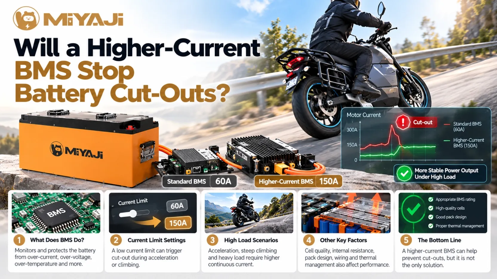
An electric motorcycle loses power during acceleration. The battery still has charge, and the vehicle starts again after the load is removed.
One suggestion often follows: “Install a higher-current BMS.”
That may be appropriate in some cases. But before changing the battery management system, the cause of the interruption needs to be identified.
For commercial motorcycles and tricycles, a reliable solution requires the cells, BMS, connections and vehicle controller to operate within compatible limits.
First, Confirm What Caused the Cut-Out
The BMS can interrupt discharge for different reasons. Depending on its design, these may include excessive current, low cell voltage, excessive temperature or a detected short circuit.
Protection also involves timing. A brief event and a sustained overload may be handled differently through separate thresholds and delays. Manufacturer documentation describes these as distinct protection functions.
If a low-voltage condition caused the interruption, a higher-current BMS does not address that cause. The same applies to a damaged connector or an overheating component.
The first question should therefore be:
“Which condition triggered the interruption, and what happened immediately before it?”
Where available, review BMS and controller fault records alongside current, cell-group voltage and temperature measurements.
What Does the BMS Current Rating Mean?
A continuous-current rating describes operation under specified conditions. A peak-current rating describes a higher current permitted for a limited period.
Neither figure is complete without its conditions.
When comparing BMS specifications, confirm:
Specification | What to clarify |
|---|---|
Continuous discharge current | Temperature, cooling and installation conditions |
Peak discharge current | Permitted duration and repetition |
Overcurrent protection | Threshold, detection delay and recovery behaviour |
Charge current | Permitted charging current, separately from discharge |
Temperature limits | Monitored components and limiting behaviour |
A board tested in favourable cooling conditions may behave differently inside a sealed battery enclosure.
Also, an overcurrent protection threshold is not a recommended continuous operating current. Protection settings and normal operating capability serve different purposes.
The Complete Pack Must Support the Current
A higher-rated BMS does not increase the safe operating capability of every other component.
The required current must also be supported by:
- The cells and their parallel arrangement.
- Internal connections and conductors.
- Output cables and terminals.
- Connectors and switching components.
- The pack’s thermal design.
BMS operating limits should remain consistent with cell specifications. Orion’s documentation, for example, states that configured cell discharge limits should not exceed the cell manufacturer’s maximum.
If the existing BMS correctly protects a pack from excessive demand, replacing it with one that allows more current may simply expose another limitation.
Check Which Controller Current Is Being Compared
Controller specifications can show battery current and motor phase current. These are different measurements.
Battery current is drawn from the pack. Phase current flows through the motor windings. Their relationship changes with operating conditions and controller behaviour.
For BMS matching, compare the relevant battery-side demand with the pack’s discharge capability.
A quoted controller current without a clear definition can lead to incorrect selection. Before choosing a BMS, confirm which current is specified and how the controller limits it.
When Can a Higher-Current BMS Be Appropriate?
A different BMS may be appropriate when testing confirms that:
- The existing BMS cannot support the intended battery-side demand.
- The cells and complete current path can safely support that demand.
- The replacement suits the chemistry, series configuration and voltage range.
- Its protection, thermal behaviour and interfaces meet the application requirements.
- The revised pack is validated under relevant conditions.
Even then, matching may involve the controller as well as the battery.
In some projects, adjusting vehicle demand is more appropriate than allowing the battery to deliver more current. The decision should follow the operating requirement and measured limits.
Similar Symptoms Can Need Different Solutions
Finding | Appropriate investigation |
|---|---|
Recorded discharge overcurrent | Compare measured demand, permitted current and protection timing |
One cell group drops to its voltage limit | Check cell condition, balance and behaviour under load |
Connector heating or excessive voltage drop | Inspect the connection and its suitability |
Temperature protection | Investigate heat sources, cooling and sensor readings |
Interruption immediately after battery connection | Check the connection sequence and any precharge requirements |
No corresponding BMS fault | Investigate controller, wiring, power supply and communication faults |
These are diagnostic directions, not automatic repair instructions. More than one issue may contribute to the same event.
Why Swapping Operators Need to Check More Than Current
Changing the BMS in a swapping battery can also affect communication, battery identification, charge control and fault reporting.
A replacement that supports higher discharge current may still be incompatible with the cabinet or management system.
Before introducing a revised configuration, check its operation across the vehicle, charger, cabinet and software interfaces that the project uses. Keep configuration records so technicians can distinguish old and new versions.
For a fleet, uncontrolled changes can make later diagnosis much harder.
Choosing the Right Configuration for a MIYAJI Project
MIYAJI connects battery PACK manufacturing with commercial vehicles, swapping cabinets, charging equipment and management software.
BMS selection belongs within that complete system. The objective is to support the intended operation while preserving suitable protection and compatibility.
When discussing your project with MIYAJI, provide the vehicle and controller specifications, typical load, routes, daily operating hours and charging or swapping requirements.
These details help establish what the battery needs to deliver—and whether a proposed BMS configuration is appropriate.
Frequently Asked Questions
Is a higher-current BMS always better?
No. It must suit the cells, pack construction, vehicle demand and system interfaces. A larger rating alone does not establish better performance.
Can raising the overcurrent threshold stop cut-outs?
It may prevent a particular protection event, but it does not establish that operation is safe or reliable. Identify the cause and verify component limits before changing settings.
Can a battery cut out below its advertised current rating?
Yes. Other protection conditions may be involved. Installation temperature, rating conditions and brief events missed by the measurement equipment also need investigation.
Does replacing the BMS require vehicle and cabinet testing?
For an integrated swapping project, relevant interfaces and operating functions should be rechecked. The extent depends on what changed.
Next in the series: Why Does an Electric Motorcycle Stop When the Battery Display Still Shows 30%?